|
[ Chapter start ] [ Previous page ] [ Next page ] 1.4 Economics of ASICsIn this section we shall discuss the economics of using ASICs in a product and compare the most popular types of ASICs: an FPGA, an MGA, and a CBIC. To make an economic comparison between these alternatives, we consider the ASIC itself as a product and examine the components of product cost: fixed costs and variable costs. Making cost comparisons is dangerous—costs change rapidly and the semiconductor industry is notorious for keeping its costs, prices, and pricing strategy closely guarded secrets. The figures in the following sections are approximate and used to illustrate the different components of cost. 1.4.1 Comparison Between ASIC TechnologiesThe most obvious economic factor in making a choice between the different ASIC types is the part cost . Part costs vary enormously—you can pay anywhere from a few dollars to several hundreds of dollars for an ASIC. In general, however, FPGAs are more expensive per gate than MGAs, which are, in turn, more expensive than CBICs. For example, a 0.5 m m, 20 k-gate array might cost 0.01–0.02 cents/gate (for more than 10,000 parts) or $2–$4 per part, but an equivalent FPGA might be $20. The price per gate for an FPGA to implement the same function is typically 2–5 times the cost of an MGA or CBIC. Given that an FPGA is more expensive than an MGA, which is more expensive than a CBIC, when and why does it make sense to choose a more expensive part? Is the increased flexibility of an FPGA worth the extra cost per part? Given that an MGA or CBIC is specially tailored for each customer, there are extra hidden costs associated with this step that we should consider. To make a true comparison between the different ASIC technologies, we shall quantify some of these costs. 1.4.2 Product CostThe total cost of any product can be separated into fixed costs and variable costs :
Fixed costs are independent of sales volume —the number of products sold. However, the fixed costs amortized per product sold (fixed costs divided by products sold) decrease as sales volume increases. Variable costs include the cost of the parts used in the product, assembly costs, and other manufacturing costs. Let us look more closely at the parts in a product. If we want to buy ASICs to assemble our product, the total part cost is
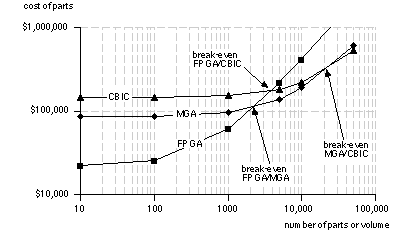
Our fixed cost when we use an FPGA is low—we just have to buy the software and any programming equipment. The fixed part costs for an MGA or CBIC are higher and include the costs of the masks, simulation, and test program development. We shall discuss these extra costs in more detail in Sections 1.4.3 and 1.4.4. Figure 1.11 shows a break-even graph that compares the total part cost for an FPGA, MGA, and a CBIC with the following assumptions:
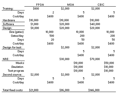
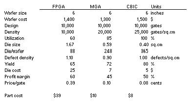
At low volumes, the MGA and the CBIC are more expensive because of their higher fixed costs. The total part costs of two alternative types of ASIC are equal at the break-even volume . In Figure 1.11 the break-even volume for the FPGA and the MGA is about 2000 parts. The break-even volume between the FPGA and the CBIC is about 4000 parts. The break-even volume between the MGA and the CBIC is higher—at about 20,000 parts. We shall describe how to calculate the fixed part costs next. Following that we shall discuss how we came up with cost per part of $39, $10, and $8 for the FPGA, MGA, and CBIC. 1.4.3 ASIC Fixed CostsFigure 1.12 shows a spreadsheet, “Fixed Costs,” that calculates the fixed part costs associated with ASIC design.
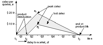
The training cost includes the cost of the time to learn any new electronic design automation ( EDA ) system. For example, a new FPGA design system might require a few days to learn; a new gate-array or cell-based design system might require taking a course. Figure 1.12 assumes that the cost of an engineer (including overhead, benefits, infrastructure, and so on) is between $100,000 and $200,000 per year or $2000 to $4000 per week (in the United States in 1990s dollars). Next we consider the hardware and software cost for ASIC design. Figure 1.12 shows some typical figures, but you can spend anywhere from $1000 to $1 million (and more) on ASIC design software and the necessary infrastructure. We try to measure productivity of an ASIC designer in gates (or transistors) per day. This is like trying to predict how long it takes to dig a hole, and the number of gates per day an engineer averages varies wildly. ASIC design productivity must increase as ASIC sizes increase and will depend on experience, design tools, and the ASIC complexity. If we are using similar design methods, design productivity ought to be independent of the type of ASIC, but FPGA design software is usually available as a complete bundle on a PC. This means that it is often easier to learn and use than semicustom ASIC design tools. Every ASIC has to pass a production test to make sure that it works. With modern test tools the generation of any test circuits on each ASIC that are needed for production testing can be automatic, but it still involves a cost for design for test . An FPGA is tested by the manufacturer before it is sold to you and before you program it. You are still paying for testing an FPGA, but it is a hidden cost folded into the part cost of the FPGA. You do have to pay for any programming costs for an FPGA, but we can include these in the hardware and software cost. The nonrecurring-engineering ( NRE ) charge includes the cost of work done by the ASIC vendor and the cost of the masks. The production test uses sets of test inputs called test vectors , often many thousands of them. Most ASIC vendors require simulation to generate test vectors and test programs for production testing, and will charge for a test-program development cost . The number of masks required by an ASIC during fabrication can range from three or four (for a gate array) to 15 or more (for a CBIC). Total mask costs can range from $5000 to $50,000 or more. The total NRE charge can range from $10,000 to $300,000 or more and will vary with volume and the size of the ASIC. If you commit to high volumes (above 100,000 parts), the vendor may waive the NRE charge. The NRE charge may also include the costs of software tools, design verification, and prototype samples. If your design does not work the first time, you have to complete a further design pass ( turn or spin ) that requires additional NRE charges. Normally you sign a contract (sign off a design) with an ASIC vendor that guarantees first-pass success—this means that if you designed your ASIC according to rules specified by the vendor, then the vendor guarantees that the silicon will perform according to the simulation or you get your money back. This is why the difference between semicustom and full-custom design styles is so important—the ASIC vendor will not (and cannot) guarantee your design will work if you use any full-custom design techniques. Nowadays it is almost routine to have an ASIC work on the first pass. However, if your design does fail, it is little consolation to have a second pass for free if your company goes bankrupt in the meantime. Figure 1.13 shows a profit model that represents the profit flow during the product lifetime . Using this model, we can estimate the lost profit due to any delay. Suppose we have the following situation:
The simple profit and revenue model of Figure 1.13 shows us that we would lose $35 million in sales in this situation due to a 3-month delay. Despite the obvious problems with such a simple model (how can we introduce the same product twice to compare the performance?), it is widely used in marketing. In the electronics industry product lifetimes continue to shrink. In the PC industry it is not unusual to have a product lifetime of 18 months or less. This means that it is critical to achieve a rapid design time (or high product velocity ) with no delays. The last fixed cost shown in Figure 1.12 corresponds to an “insurance policy.” When a company buys an ASIC part, it needs to be assured that it will always have a back-up source, or second source , in case something happens to its first or primary source. Established FPGA companies have a second source that produces equivalent parts. With a custom ASIC you may have to do some redesign to transfer your ASIC to the second source. However, for all ASIC types, switching production to a second source will involve some cost. Figure 1.12 assumes a second-source cost of $2000 for all types of ASIC (the amount may be substantially more than this). 1.4.4 ASIC Variable CostsFigure 1.14 shows a spreadsheet, “Variable Costs,” that calculates some example part costs. This spreadsheet uses the terms and parameters defined below the figure.
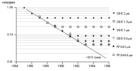
As an estimate you can assume that the price per gate for any process technology falls at about 20 % per year during its life (the average life of a CMOS process is 2–4 years, and can vary widely). Beyond the life of a process, prices can increase as demand falls and the fabrication equipment becomes harder to maintain. Figure 1.15 shows the price per gate for the different ASICs and process technologies using the following assumptions:
From Figure 1.15 you can see that the successive introduction of new process technologies every 2 years drives the price per gate down at a rate close to 30 percent per year. The cost figures that we have used in this section are very approximate and can vary widely (this means they may be off by a factor of 2 but probably are correct within a factor of 10). ASIC companies do use spreadsheet models like these to calculate their costs. Having decided if, and then which, ASIC technology is appropriate, you need to choose the appropriate cell library. Next we shall discuss the issues surrounding ASIC cell libraries: the different types, their sources, and their contents. |
|||||||||||
|
|
|||||||||||
|
|||||||||||

