|
Chapter start Previous page Next page 10.5 Entities and ArchitecturesThe highest-level VHDL construct is the design file [VHDL LRM11.1]. A design file contains design units that contain one or more library units. Library units in turn contain: entity, configuration, and package declarations (primary units); and architecture and package bodies (secondary units). design_file ::=
{library_clause|use_clause} library_unit
{{library_clause|use_clause} library_unit}
library_unit ::= primary_unit|secondary_unit
primary_unit ::=
entity_declaration|configuration_declaration|package_declaration
secondary_unit ::= architecture_body|package_body
Using the written language analogy: a VHDL library unit is a "book," a VHDL design file is a "bookshelf," and a VHDL library is a collection of bookshelves. A VHDL primary unit is a little like the chapter title and contents that appear on the first page of each chapter in this book and a VHDL secondary unit is like the chapter contents (though this is stretching our analogy a little far). I shall describe the very important concepts of entities and architectures in this section and then cover libraries, packages, and package bodies. You define an entity, a black box, using an entity declaration [VHDL LRM1.1]. This is the BNF definition: entity_declaration ::=
entity identifier is
[generic (formal_generic_interface_list);]
[port (formal_port_interface_list);]
{entity_declarative_item}
[begin
{[label:] [postponed] assertion ;
|[label:] [postponed] passive_procedure_call ;
|passive_process_statement}]
end [entity] [entity_identifier] ;
The following is an example of an entity declaration for a black box with two inputs and an output: entity Half_Adder is port (X, Y : in BIT := '0'; Sum, Cout : out BIT); -- formals end; Matching the parts of this
code with the constructs in BNF [10.7] you can see that the The architecture body [VHDL LRM1.2] describes what an entity does, or the contents of the black box (it is architecture body and not architecture declaration). architecture_body ::=
architecture identifier of entity_name is
{block_declarative_item}
begin
{concurrent_statement}
end [architecture] [architecture_identifier] ;
For example, the following architecture
body (I shall just call it an architecture from now on) describes the contents
of the entity architecture Behave of Half_Adder is begin Sum <= X xor Y; Cout <= X and Y; end Behave; We use the same signal names
(the formals: Why would we want to describe the outside of a black box (an entity) separately from the description of its contents (its architecture)? Separating the two makes it easier to move between different architectures for an entity (there must be at least one). For example, one architecture may model an entity at a behavioral level, while another architecture may be a structural model. A structural model that uses an entity in an architecture must declare that entity and its interface using a component declaration as follows [VHDL LRM4.5]: component_declaration ::= component identifier [is] [generic (local_generic_interface_list);] [port (local_port_interface_list);] end component [component_identifier]; For example, the following architecture,
architecture Netlist of Half_Adder is
component MyXor port (A_Xor,B_Xor : in BIT; Z_Xor : out BIT);
end component; -- component with locals
component MyAnd port (A_And,B_And : in BIT; Z_And : out BIT);
end component; -- component with locals
begin
	Xor1: MyXor port map (X, Y, Sum); 															-- instance with actuals
	And1 : MyAnd port map (X, Y, Cout); 															-- instance with actuals
end;
Next we define the entities
and architectures that we shall use for the components We do not need to write VHDL
code for -- These definitions are part of a technology library: entity AndGate is port (And_in_1, And_in_2 : in BIT; And_out : out BIT); -- formals end; architecture Simple of AndGate is begin And_out <= And_in_1 and And_in_2; end; entity XorGate is port (Xor_in_1, Xor_in_2 : in BIT; Xor_out : out BIT); -- formals end; architecture Simple of XorGate is begin Xor_out <= Xor_in_1 xor Xor_in_2; end; If we keep the description of
a circuit's interface configuration_declaration ::=
configuration identifier of entity_name is
{use_clause|attribute_specification|group_declaration}
block_configuration
end [configuration] [configuration_identifier] ;
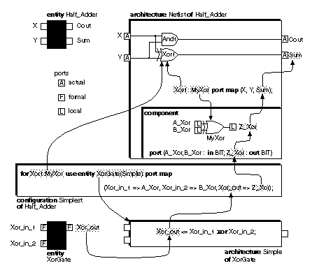
An entity-architecture pair is a design entity. The following configuration declaration defines which design entities we wish to use and associates the formal ports (from the entity declaration) with the local ports (from the component declaration): configuration Simplest of Half_Adder is use work.all; for Netlist for And1 : MyAnd use entity AndGate(Simple) port map -- association: formals => locals (And_in_1 => A_And, And_in_2 => B_And, And_out => Z_And); end for; for Xor1 : MyXor use entity XorGate(Simple) port map (Xor_in_1 => A_Xor, Xor_in_2 => B_Xor, Xor_out => Z_Xor); end for; end for; end; Figure 10.1 diagrams the use of entities, architectures, components, and configurations. This figure seems very complicated, but there are two reasons that VHDL works this way:
You can think of design units, the analyzed entity-architecture pairs, as compiled object-code modules. The configuration then determines which object-code modules are linked together to form executable binary code. You may also think of an entity as a block diagram, an architecture for an entity a more detailed circuit schematic for the block diagram, and a configuration as a parts list of the circuit components with their part numbers and manufacturers (also known as a BOM for bill of materials, rather like a shopping list). Most manufacturers (including the U.S. DoD) use schematics and BOMs as control documents for electronic systems. This is part of the rationale behind the structure of VHDL. |
|||||
|
|
|||||
|
|||||


