10.7  Interface Declarations

Chapter  start   Previous page  Next  page

10.7  Interface Declarations

An interface declaration declares interface objects that may be interface constants, signals, variables, or files [VHDL 87LRM4.3.3, 93LRM4.3.2]. Interface constants are generics of a design entity, a component, or a block, or parameters of subprograms. Interface signals are ports of a design entity, component, or block, and parameters of subprograms. Interface variables and interface files are parameters of subprograms.

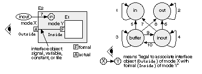
Each interface object has a mode that indicates the direction of information flow. The most common modes are in (the default), out , inout , and buffer (a fifth mode, linkage , is used to communicate with other languages and is infrequently used in ASIC design). The restrictions on the use of objects with these modes are listed in Table 10.10. An interface object is read when you use it on the RHS of an assignment statement, for example, or when the object is associated with another interface object of modes in , inout (or linkage ). An interface object is updated when you use it on the LHS side of an assignment statement or when the object is associated with another interface object of mode out , buffer , inout (or linkage ). The restrictions on reading and updating objects generate the diagram at the bottom of Table 10.10 that shows the 10 allowed types of interconnections (these rules for modes buffer and inout are the same). The interface objects ( Inside and Outside ) in the example in this table are ports (and thus interface signals), but remember that interface objects may also be interface constants, variables, and files.

TABLE 10.10    Modes of interface objects and their properties.

entity E1 is port (Inside : in BIT); end; architecture Behave of E1 is begin end;
entity E2 is port (Outside : inout BIT := '1'); end; architecture Behave of E2 is 
component E1 port (Inside: in BIT); end component; signal UpdateMe : BIT; begin 
I1 : E1 port map (Inside => Outside); -- formal/local (mode in) => actual (mode inout)
UpdateMe <= Outside; -- OK to read Outside (mode inout)
Outside  <= '0' after 10 ns; -- and OK to update Outside (mode inout)
end;

Possible modes of interface object, Outside

in (default) out inout buffer

Can you read Outside (RHS of assignment)?

Yes No Yes Yes

Can you update Outside (LHS of assignment)?

No Yes Yes Yes

Modes of Inside that Outside may connect to (see below) 1

in out any any


There are other special-case rules for reading and updating interface signals, constants, variables, and files that I shall cover in the following sections. The situation is like the spelling rule, "i before e except after c." Table 10.10 corresponds to the rule "i before e."

10.7.1  Port Declaration

Interface objects that are signals are called ports [VHDL 93LRM1.1.1.2]. You may think of ports as "connectors" and you must declare them as follows:

port (port_interface_list)
interface_list ::=
	port_interface_declaration {; port_interface_declaration}

A port interface declaration is a list of ports that are the inputs and outputs of an entity, a block, or a component declaration:

interface_declaration ::=
	[signal] 
		identifier {, identifier}:[in|out|inout|buffer|linkage]
		subtype_indication [bus] [:= static_expression]

Each port forms an implicit signal declaration and has a port mode. I shall discuss bus , which is a signal kind, in Section 10.13.1. Here is an example of an entity declaration that has five ports:

entity Association_1 is 
	port (signal X, Y : in BIT := '0'; Z1, Z2, Z3 : out BIT);
end;

In the preceding declaration the keyword signal is redundant (because all ports are signals) and may be omitted. You may also omit the port mode in because it is the default mode. In this example, the input ports X and Y are driven by a default value (in general a default expression) of '0' if (and only if ) the ports are left unconnected or open. If you do leave an input port open, the port must have a default expression.

You use a port map and either positional association or named association to connect the formals of an entity with the locals of a component. Port maps also associate (connect) the locals of a component with the actuals of an instance. For an example of formal, local, and actual ports, and explanation of their function, see Section 10.5, where we declared an entity AndGate. The following example shows how to bind a component to the entity AndGate (in this case we use the default binding) and associate the ports. Notice that if we mix positional and named association then all positional associations must come first.

use work.all; -- makes analyzed design entity AndGate(Simple) visible.
architecture Netlist of Association_1 is
-- The formal port clause for entity AndGate looks like this:
-- port (And_in_1, And_in_2: in BIT; And_out : out BIT); -- Formals.
component AndGate port 
	(And_in_1, And_in_2 : in BIT; And_out : out BIT); -- Locals.
end component;
begin
-- The component and entity have the same names: AndGate.
-- The port names are also the same: And_in_1, And_in_2, And_out,
-- so we can use default binding without a configuration.
-- The last (and only) architecture for AndGate will be used: Simple.
A1:AndGate port map (X, Y, Z1); -- positional association
A2:AndGate port map (And_in_2=>Y, And_out=>Z2, And_in_1=>X);																									-- named
A3:AndGate port map (X, And_out => Z3, And_in_2 => Y);																									-- both
end;

The interface object rules of Table 10.10 apply to ports. The rule that forbids updating an interface object of mode in prevents modifying an input port (by placing the input signal on the left-hand side of an assignment statement, for example). Less obviously, you cannot read a port of mode out (that is you cannot place an output signal on the right-hand side of an assignment statement). This stops you from accidentally reading an output signal that may be connected to a net with multiple drivers. In this case the value you would read (the unresolved output signal) might not be the same as the resolved signal value. For example, in the following code, since Clock is a port of mode out , you cannot read Clock directly. Instead you can transfer Clock to an intermediate variable and read the intermediate variable instead:

entity ClockGen_1 is port (Clock : out BIT); end;
architecture Behave of ClockGen_1 is
begin process variable Temp : BIT := '1';
	begin
--	Clock <= not Clock; -- Illegal, you cannot read Clock (mode out),
	Temp := not Temp; -- use a temporary variable instead.
	Clock <= Temp after 10 ns; wait for 10 ns;
	if (now > 100 ns) then wait; end if; end process;
end;

TABLE 10.11    Properties of ports.

Example entity declaration:

entity E is port (F_1:BIT; F_2:out BIT; F_3:inout BIT; F_4:buffer BIT); end;  -- formals

Example component declaration:

component C port (L_1:BIT; L_2:out BIT; L_3:inout BIT; L_4:buffer BIT); -- locals
end component;

Example component instantiation:

I1 : C port map 
(L_1 => A_1, L_2 => A_2, L_3 => A_3, L_4 => A_4); -- locals => actuals

Example configuration:

for I1 : C use entity E(Behave) port map 
(F_1 => L_1, F_2 => L_2, F_3 => L_3, F_4 => L_4); -- formals => locals

Interface object, port F

 F_1
 F_2
 F_3
 F_4

Mode of F

in (default)

out inout buffer

Can you read attributes of F?

[VHDL LRM4.3.2]

Yes, but not the attributes:

'STABLE

'QUIET

'DELAYED

'TRANSACTION

Yes, but not the attributes:

'STABLE 'QUIET

'DELAYED

'TRANSACTION

'EVENT 'ACTIVE

'LAST_EVENT

'LAST_ACTIVE

'LAST_VALUE

Yes, but not the attributes:

'STABLE

'QUIET

'DELAYED

'TRANSACTION

Yes

Table 10.10 lists the restrictions on reading and updating interface objects including interface signals that form ports. Table 10.11 lists additional special rules for reading and updating the attributes of interface signals.

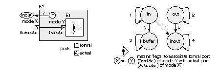
There is one more set of rules that apply to port connections [VHDL LRM 1.1.1.2]. If design entity E2 contains an instance, I1 , of design entity E1 , then the formals (of design entity E1 ) are associated with actuals (of instance I1 ). The actuals (of instance I1 ) are themselves formal ports (of design entity E2 ). The restrictions illustrated in Table 10.12 apply to the modes of the port connections from E1 to E2 (looking from the inside to the outside).

Notice that the allowed connections diagrammed in Table 10.12 (looking from inside to the outside) are a superset of those of Table 10.10 (looking from the outside to the inside). Only the seven types of connections shown in Table 10.12 are allowed between the ports of nested design entities. The additional rule that ports of mode buffer may only have one source, together with the restrictions on port mode interconnections, limits the use of ports of mode buffer .

TABLE 10.12    Connection rules for port modes.

 entity E1 is port (Inside : in BIT); end; architecture Behave of E1 is begin end;
entity E2 is port (Outside : inout BIT := '1'); end; architecture Behave of E2 is 
component E1 port (Inside : in BIT); end component; begin 
I1 : E1 port map (Inside => Outside); 																-- formal/local (mode in) => actual (mode inout)
end;

Possible modes of interface object, Inside

in (default)

out

inout buffer

Modes of Outside that Inside may connect to (see below)

in  inout  buffer

out  inout

inout 2

buffer 3


10.7.2  Generics

Ports are signals that carry changing information between entities. A generic is similar to a port, except generics carry constant, static information [VHDL LRM1.1.1.1]. A generic is an interface constant that, unlike normal VHDL constants, may be given a value in a component instantiation statement or in a configuration specification. You declare generics in an entity declaration and you use generics in a similar fashion to ports. The following example uses a generic parameter to alter the size of a gate:

entity AndGateNWide is 
	generic (N : NATURAL := 2);
	port (Inputs : BIT_VECTOR(1 to N); Result : out BIT); 
end;

Notice that the generic interface list precedes the port interface list. Generics are useful to carry timing (delay) information, as in the next example:

entity AndT is 
	generic (TPD : TIME := 1 ns);
	port (a, b : BIT := '0'; q: out BIT);
end;
architecture Behave of AndT is 
	begin q <= a and b after TPD;
end;
entity AndT_Test_1 is end;
architecture Netlist_1 of AndT_Test_1 is 
	component MyAnd 
		port (a, b : BIT; q : out BIT);
	end component;
	signal a1, b1, q1 : BIT := '1';
	begin 
		And1 : MyAnd port map (a1, b1, q1);
end Netlist_1;
configuration Simplest_1 of AndT_Test_1 is use work.all;
	for Netlist_1 for And1 : MyAnd 
		use entity AndT(Behave) generic map (2 ns); 
	end for; end for;
end Simplest_1;

The configuration declaration, Simplest_1, changes the default delay (equal to 1 ns, declared as a default expression in the entity) to 2 ns. Techniques based on this method are useful in ASIC design. Prelayout simulation uses the default timing values. Back-annotation alters the delay in the configuration for postlayout simulation. When we change the delay we only need to reanalyze the configuration, not the rest of the ASIC model.

There was initially no standard in VHDL for how timing generics should be used, and the lack of a standard was a major problem for ASIC designers. The IEEE 1076.4 VITAL standard addresses this problem (see Section 13.5.5).


1. There are additional rules for interface objects that are signals (ports)--see Tables 10.11 and 10.12.

2. A signal of mode inout can be updated by any number of sources [VHDL 87LRM4.3.3, 93LRM4.3.2].

3. A signal of mode buffer can be updated by at most one source [VHDL LRM1.1.1.2].


Chapter  start   Previous  page   Next  page


© 2025 Internet Business Systems, Inc.
670 Aberdeen Way, Milpitas, CA 95035
+1 (408) 882-6554 — Contact Us, or visit our other sites:
AECCafe - Architectural Design and Engineering EDACafe - Electronic Design Automation GISCafe - Geographical Information Services TechJobsCafe - Technical Jobs and Resumes ShareCG - Share Computer Graphic (CG) Animation, 3D Art and 3D Models
  Privacy PolicyAdvertise