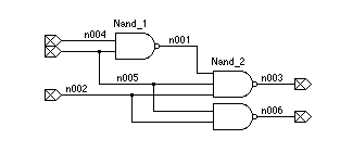
11.9 Logic-Gate ModelingVerilog has a set of built-in logic models and you may also define your own models. 11.9.1 Built-in Logic ModelsVerilog's built-in logic models are the following primitives [Verilog LRM7]: You may use these primitives as you use modules. For example: module primitive; nand (strong0, strong1) #2.2 Nand_1(n001, n004, n005), Nand_2(n003, n001, n005, n002); nand (n006, n005, n002); endmodule This module models three NAND
gates (Figure 11.2). The first gate (line
3) is a two-input gate named
Table 11.5
shows the definition of the 11.9.2 User-Defined PrimitivesWe can define primitive
gates (a user-defined primitive or UDP) using a truth-table
specification [Verilog LRM8]. The first port of a UDP must be an primitive Adder(Sum, InA, InB); output Sum; input Ina, InB; table // inputs : output 00 : 0; 01 : 1; 10 : 1; 11 : 0; endtable endprimitive We may only specify the values
We can construct a UDP model for sequential logic by including a state in the UDP truth-table definition. The state goes between an input and an output in the table and the output then represents the next state. The following sequential UDP model also illustrates the use of shorthand notation in a UDP truth table: primitive DLatch(Q, Clock, Data); output Q; reg Q; input Clock, Data; table //inputs : present state : output (next state) 1 0 : ? : 0; // ? represents 0,1, or x (input or present state). 1 1 : b : 1; // b represents 0 or 1 (input or present state). 1 1 : x : 1; // Could have combined this with previous line. 0 ? : ? : -; // - represents no change in an output. endtable endprimitive Be careful not to confuse
the For sequential UDP models that
need to detect edge transitions on inputs, there is another special truth-table
notation primitive DFlipFlop(Q, Clock, Data); output Q; reg Q; input Clock, Data; table //inputs : present state : output (next state) r 0 : ? : 0 ; // rising edge, next state = output = 0 r 1 : ? : 1 ; // rising edge, next state = output = 1 (0x) 0 : 0 : 0 ; // rising edge, next state = output = 0 (0x) 1 : 1 : 1 ; // rising edge, next state = output = 1 (?0) ? : ? : - ; // falling edge, no change in output ? (??) : ? : - ; // no clock edge, no change in output endtable endprimitive |
|||||||||||||||||||||||||||||||||
|
|
|||||||||||||||||||||||||||||||||
|
|||||||||||||||||||||||||||||||||


