|
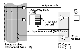
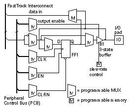
[ Chapter start ] [ Previous page ] [ Next page ] 6.8 Other I/O CellsThe Altera MAX 5000 and 7000 use the I/O Control Block ( IOC ) shown in Figure 6.23 . In the MAX 5000, all inputs pass through the chipwide interconnect. The MAX 7000E has special fast inputs that are connected directly to macrocell registers in order to reduce the setup time for registered inputs. The FLEX 8000 and 10k use the I/O Element ( IOE ) shown in Figure 6.24 (the MAX 9000 IOC is similar). The interface to the IOE is directly to the chipwide interconnect rather than the core logic. There is a separate bus, the Peripheral Control Bus , for the IOE control signals: clock, preset, clear, and output enable. The AMD MACH 5 family has some I/O features not currently found on other programmable ASICs. The MACH 5 family has 3.3 V and 5 V versions that are both suitable for mixed-voltage designs. The 3 V versions accept 5 V inputs, and the outputs of the 3 V versions do not drive above 3.3 V. You can apply a voltage up to 5.5 V to device inputs before you connect VDD (this is known as hot insertion or hot switching, allowing you to swap cards with power still applied without causing latch-up). During power-up and power-down, all I/Os are three-state, and there is no I/O current during power-down, allowing power-down while connected to an active bus. All MACH 5 devices in the same package have the same pin configuration, so you can increase or reduce the size of device after completing the board layout. [ Chapter start ] [ Previous page ] [ Next page ] | |


