FLOORPLANNING AND PLACEMENT
FLOORPLANNING
AND
PLACEMENT
The input to the floorplanning step is the output of system partitioning and design entry—a netlist. Floorplanning precedes placement, but we shall cover them together. The output of the placement step is a set of directions for the routing tools.
At the start of floorplanning we have a netlist describing circuit blocks, the logic cells within the blocks, and their connections. For example,
Figure 16.1
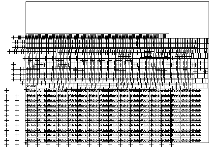
shows the Viterbi decoder example as a collection of standard cells with no room set aside yet for routing. We can think of the standard cells as a hod of bricks to be made into a wall. What we have to do now is set aside spaces (we call these spaces the
channels
) for interconnect, the mortar, and arrange the cells.
Figure 16.2
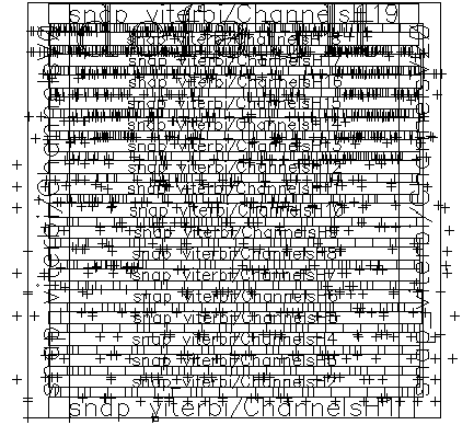
shows a finished wall—after floorplanning and placement steps are complete. We still have not completed any routing at this point—that comes later—all we have done is placed the logic cells in a fashion that we hope will minimize the total interconnect length, for example.
|

|
|
FIGURE 16.1
The starting point for the floorplanning and placement steps for the Viterbi decoder (containing only standard cells). This is the initial display of the floorplanning and placement tool. The small boxes that look like bricks are the outlines of the standard cells. The largest standard cells, at the bottom of the display (labeled dfctnb) are 188 D flip-flops. The '+' symbols represent the drawing origins of the standard cells—for the D flip-flops they are shifted to the left and below the logic cell bottom left-hand corner. The large box surrounding all the logic cells represents the estimated chip size. (This is a screen shot from Cadence Cell Ensemble.)
|
|

|
|
FIGURE 16.2
The Viterbi Decoder (from
Figure 16.1
) after floorplanning and placement. There are 18 rows of standard cells separated by 17 horizontal channels (labeled 2–18). The channels are routed as numbered. In this example, the I/O pads are omitted to show the cell placement more clearly. Figure 17.1 shows the same placement without the channel labels. (A screen shot from Cadence Cell Ensemble.)
|
[ Chapter Index ] [ Next page ] | 


